Basic Instrument Parameters
- Wavelength coverage
- 516 -- 593 nm (fixed)
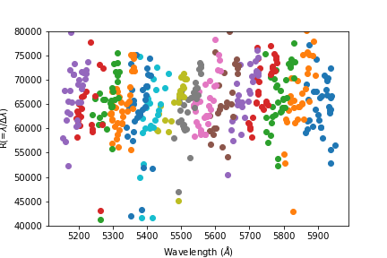
- Spectral resolution
- R ∼ 65,000 (see below for more details)
- Fiber diameter
- 130 μm = 2.2 arcsec
- Fiber length
- 35m (from Nasmyth to Spectrograph)
- Wavelength calibrators
- ThAr lamp, iodine(I2)-cell
- Throughput
- ∼ 2.5-3.0 % (see below for more details)
- Detector
- one 2k x 4k CCD (e2V CCD44-82BI), 15μm×15μm pixel
- Readout system
- M-front 2 + Messia-V
- Conversion factors
- 1.92 & 1.95 e-/ADU
- Readout noise
- ∼ 4 e-
- System Dark current
- ∼ 10 e- /pix /hour
- Saturation level
- > 51,000 ADU (within 0.05% linearity error) (see below for more details)
- Total Dead Time for Readout
- ∼ 30 sec / exposure
- Minimum exposure time
- 1 sec
- Maximum exposure time
- 3,600 sec exposures have been confirmed to work normally.
Optical Layout
Nasmyth Unit (on Seimei Telescope)
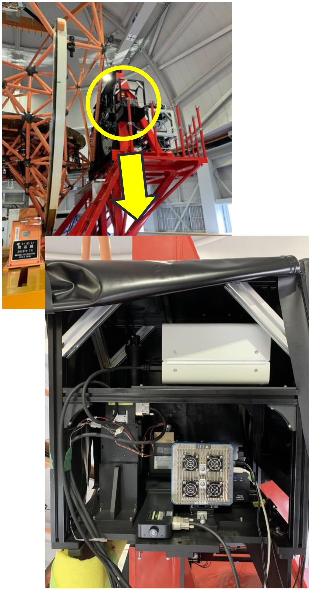
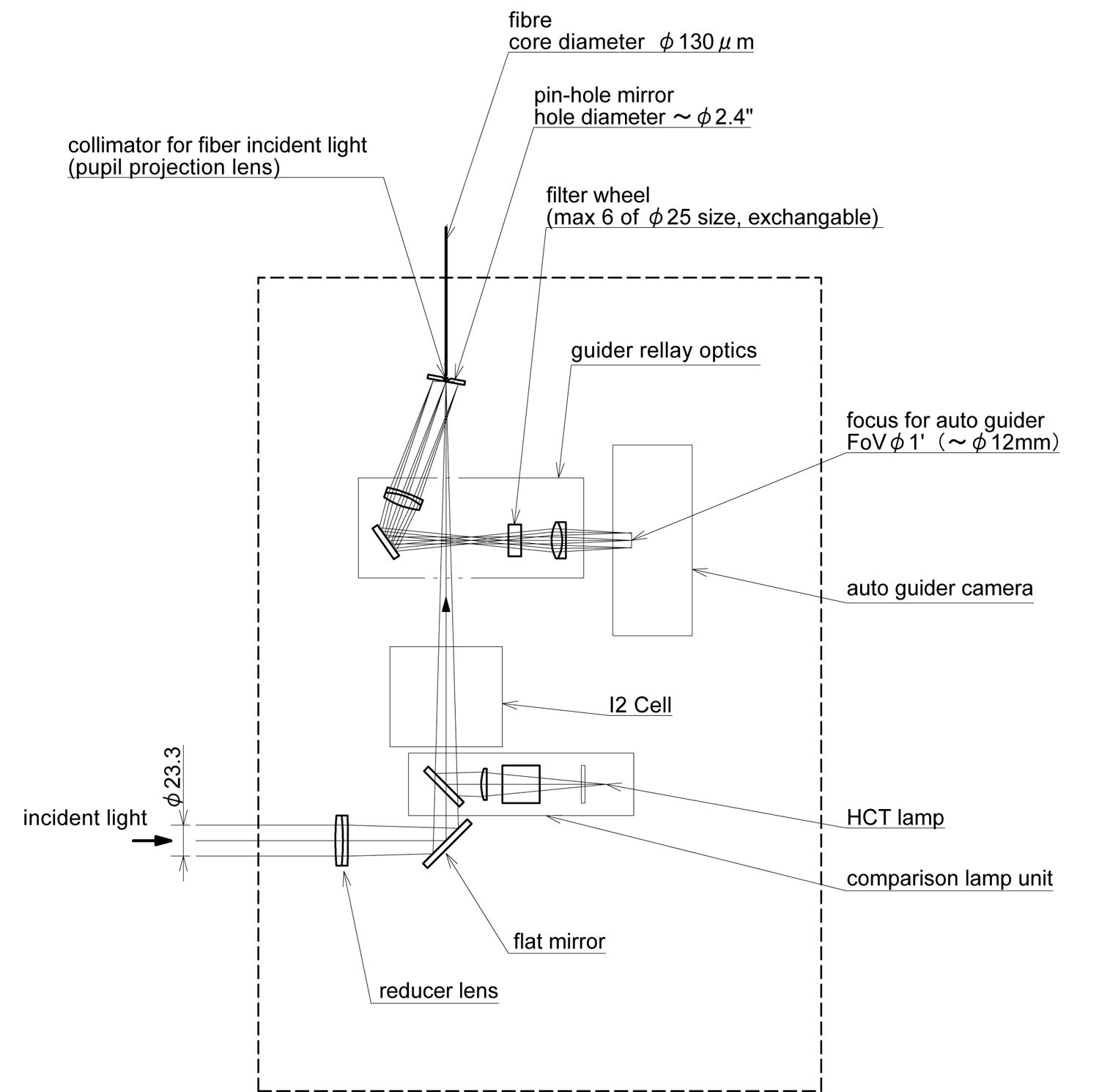
The entrance to the fiber and the guide camera system are located in a unit mounted at the Nasmyth focus (red) of the telescope. The unit also contains a calibration light source (ThAr, flat) and an I2 cell, which can be inserted into the optical path as required.
Light is introduced into the Nasmyth unit by fixing the rotator angle of the telescope (offset angle -74.9°). Therefore, during guiding, image rotation always occurs depending on the position of the telescope.
The light that entered the fiber from the pinhole is guided into the spectrograph room on the 2nd floor of the dome through a 35m long fiber.
Spectrograph (in the 2nd Floor of the dome)
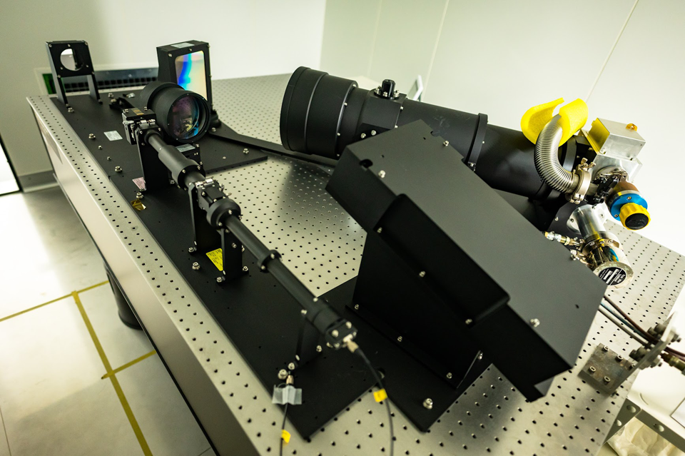
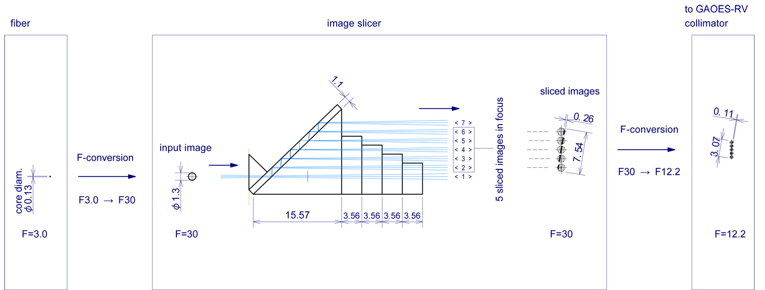
The light (F3) that has passed through the fiber is converted to F30 once and enters into the image slicer. Here, it is divided into five slice images, converted again to F12.2 for the GAOES spectrograph.
This spectrograph room is always kept at 20.0 degC by precision air conditioning, enabling stable wavelength measurement.
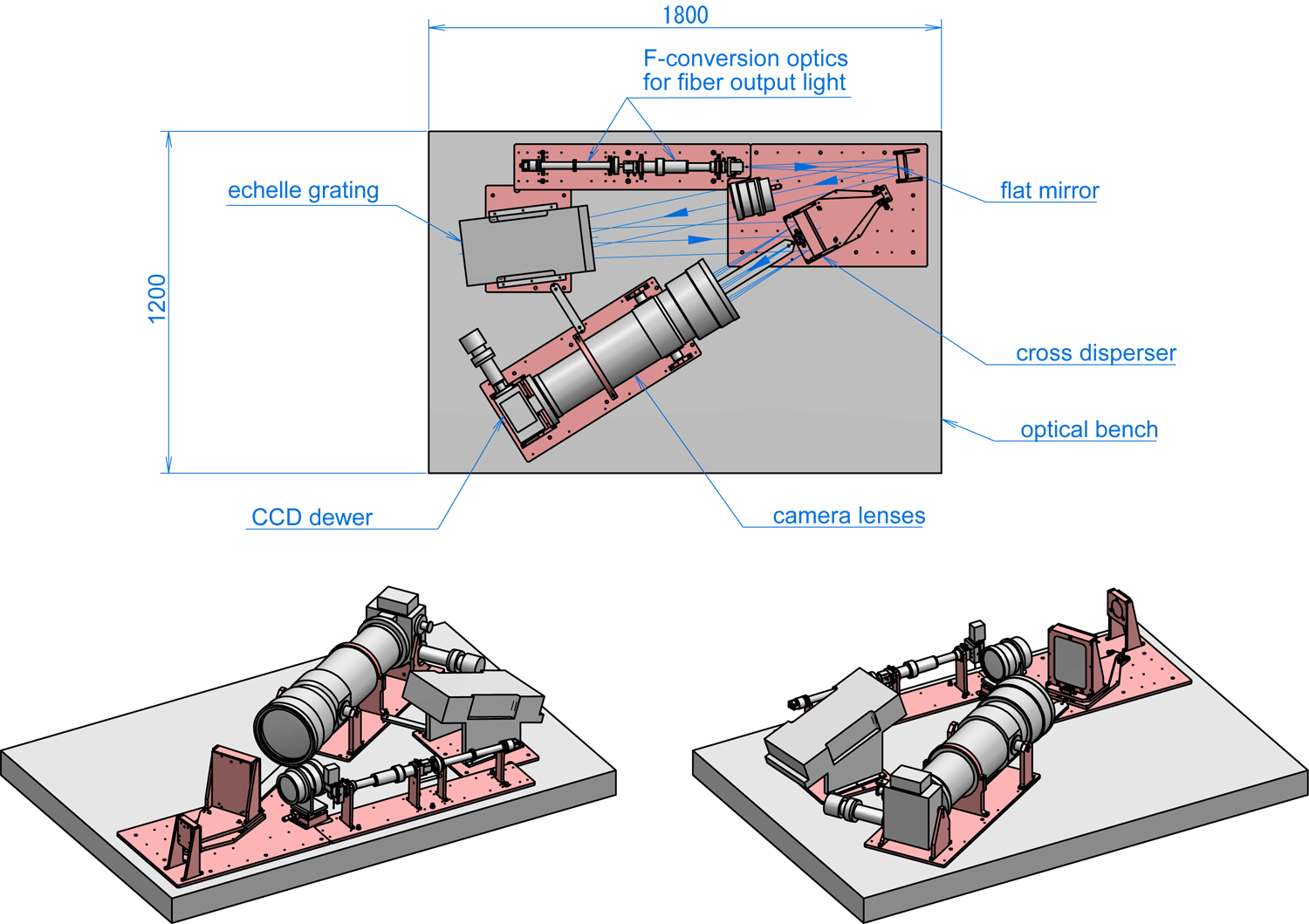
Image Slicer
The same Bowen-Wolraven type slicer element used in the Subaru/HDS and Okayama 188 cm telescope HIDES is used (for details, see Tajitsu et al. 2012, PASJ, 64, 77).
By attaching a plane-parallel plate to the output side of the slicer, five focused slice images can be obtained, and a high dispersion spectrum can be obtained using more incident photons on the fiber.
Guide Camera & Target Acquisition
Please note that if there is a bright object within about 10 arcsec of the target object, it will interfere with the guiding.
The centers of the FoV of the FoV confirmation camera (ZWO Cam) and the guide camera of GAOES-RV are well adjusted to match each other.
- FoV
- 50” × 50” (512 pixel × 512 pixel)
- Entrance aperture for the fiber
- φ2.2” (130μm, F3)
- Filters
- ND1 / ND2 / ND3 / 2 × Band-pass filters
- Limiting magnitude for Guiding
- V < 13 mag with 5 sec exposure
Throughput
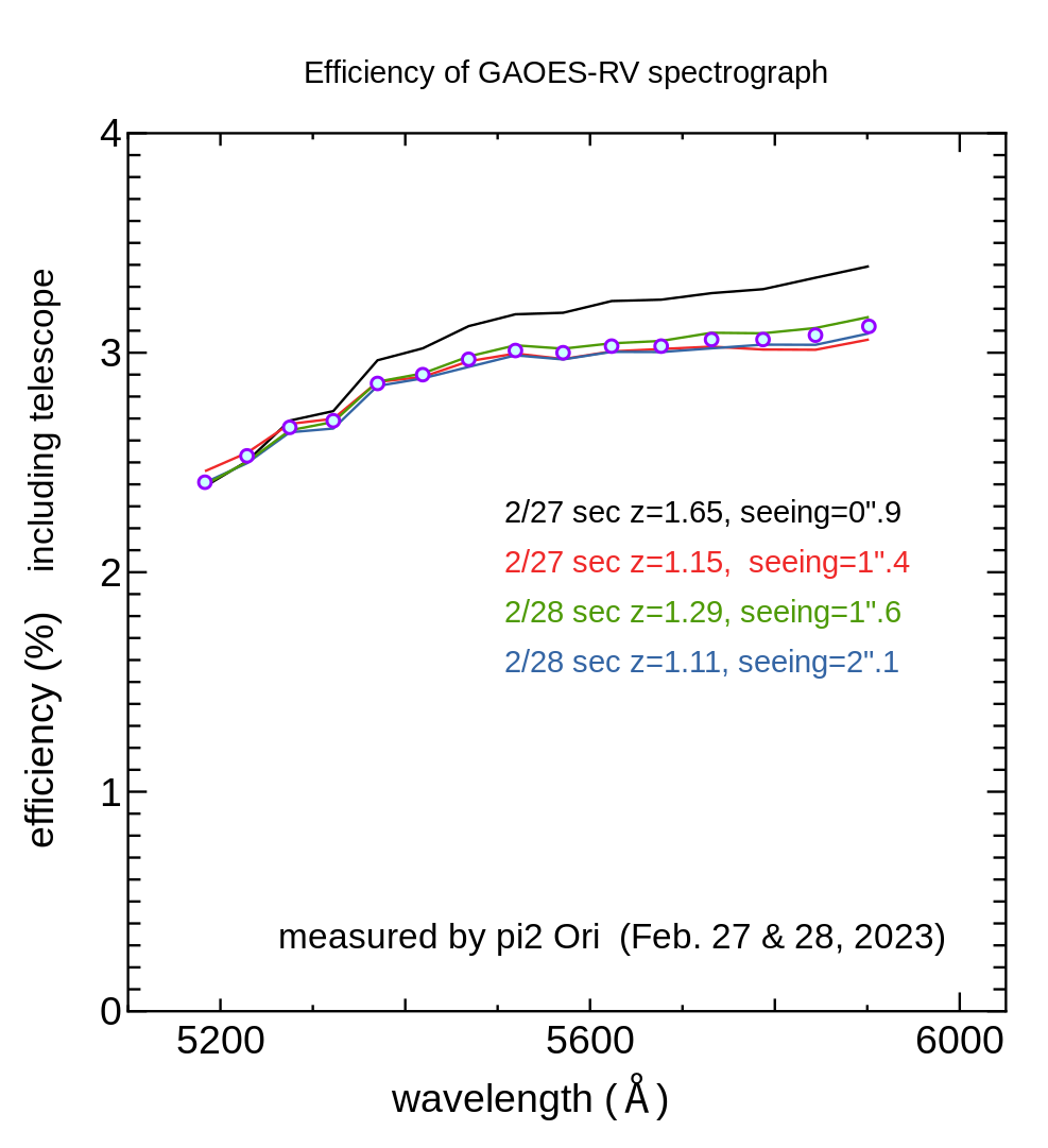
The actual observation efficiency depends on the atmospheric extinction and the efficiency of the fiber inlet,
1 - exp(ln 2 × 2.22 / seeing2)
, will be taken into consideration.The S/N ratios of objects you want to observe can be estimated with ETC.
CCD Linearity
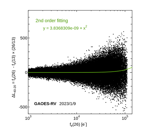
See below for the details of this test.
Spectral resolution
Stability of Spectrograph
- Dispersion direction: about 0.1 pixel (half night to overnight), about 0.5 pixel (different observation periods)
- Spatial direction: within 0.2 pixels
- Spectrograph room temperature: 21±0.1 degC
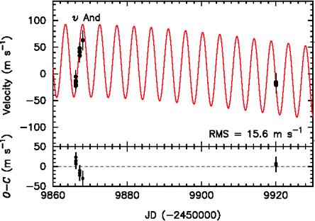
Accuracy of RV measurement
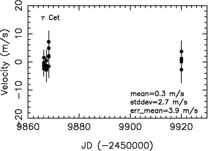
In the future, by optimizing the analysis method for GAOES-RV and improving the stability of the spectrograph, we aim to achieve the target accuracy (1m/s or less).
In addition to general analysis of high-dispersion spectra, special analysis is required for precise radial velocity measurements using the I2 cell. If you expect to use the analysis code used by the development group, we strongly recommend that you contact the instrument PI and conduct joint research.